

Customization starts with the enclosure, not the display. Before you compare panels, document the physical limits of your product housing: window size, internal depth, mounting boss locations, sealing requirements, and the thermal path away from the panel. Record display needs on the same sheet: size, resolution, interface, brightness, and touch. These two lists together define what will actually fit.
Work through the project in a fixed order. Capture requirements first, then mechanical fit, then electrical and optical performance, then environmental validation, and finally cost. Each step constrains the next, so skipping ahead forces rework.
Bring a customization partner such as Golden Vision into that first conversation. Early input on a tft display module keeps tolerance stack-ups and interface choices from triggering a costly enclosure redesign later.
Key Takeaways
- Measure your product enclosure first. Record window size, depth, and mounting points.
- Follow a fixed order: requirements, mechanical fit, electrical performance, testing, and cost.
- Bring a customization partner into the first conversation to avoid costly redesigns.
- Secure the display by clamping the frame, never the glass. Use rear studs or brackets.
- Test a prototype in the real enclosure before mass production to catch problems early.
Assess Display Panels in an Enclosure
Mechanical and Environmental Constraints
Measure the housing before you open a panel datasheet. Record the window opening, the usable internal depth behind the window, and the position of every mounting boss. Note the sealing method at the window edge and the path that heat takes away from the panel. These numbers form the hard boundary for any display panels in an enclosure.
Work through the measurement in a fixed sequence. Start with the window aperture and its corner radii. Move to the depth from the window plane to the nearest obstruction, such as a PCB or a battery. Map each boss and screw location, because these become your mounting points later. Finish with the gasket zone and the thermal route. A compact TFT display module often leaves little margin in any of these areas, so measure twice and write the values down.
Interface, Touch, and Brightness Needs
Translate the product use case into display requirements next. A handheld instrument needs a small diagonal and a narrow bezel. An outdoor kiosk needs high brightness and a wide viewing angle. A medical front panel needs a specific touch type and a clean cover glass surface. Write each need as a target value, not a preference.
Then match those targets to an lcd display module that fits the measured space. Confirm the interface type, the pin count, and the connector position against your board layout. Decide whether touch is resistive, capacitive, or absent. Set a brightness target that matches the ambient light of the real installation. This step turns a vague wish list into a specification your supplier can quote, and it keeps mechanical integration from forcing a late panel change.
Mechanical Customization of the TFT Display Module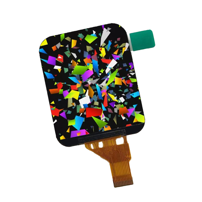
Securing TFT and OLED Display Panels
Dimensions come first. Give your supplier the measured window, depth, and boss map, and ask for a drawing that shows the panel outline, the active area, and the flex tail. FPC routing deserves its own review. The tail must bend without stress, clear the nearest obstruction, and reach the connector without a sharp fold. Route it along a flat path and leave slack for assembly.
Securing TFT and OLED display panels relies on a few proven approaches. Rear stud mounting uses threaded posts bonded to the panel frame. Integrated rear studs give you repeatable rear-side mounting points without drilling the housing. A customized TFT display module can ship with integrated rear studs placed to match your boss pattern exactly. Screw + bracket mounting suits larger panels that need edge support. Screw plus bracket mounting also spreads clamp load away from the glass. Front bezel snap-fit works well for consumer products with molded covers. Double-sided tape / adhesive bonding fits thin, low-profile designs. Double-sided tape or adhesive bonding removes fasteners entirely, yet it complicates service access.
Never press directly on the glass with screws. Never press directly on the glass with screws during prototype builds either. Clamp force belongs on the frame, not the viewing area. A compact TFT display module has little spare frame width, so confirm the clamp zone on the drawing before you cut metal.
Enclosure Mounting and Bezel Options
Enclosure mounting decisions shape the bezel. Integrated rear studs simplify enclosure mounting because the stud layout defines the hole pattern in one step. Review the rear stud position against every internal component. A clean rear stud layout keeps the panel centered and square. The integrated rear stud design also sets the standoff height, so check it against your depth measurement.
Cover glass and window integration follow. Full lamination bonds glass to the panel with optical adhesive and improves durability and contrast. Air bonding costs less and eases rework. Frame bonding attaches glass to the bezel instead. Each method changes the stack height, so update your depth budget after you choose.
Bezel design closes the loop. Golden Vision supports tooling for custom frames and gaskets, which turns your window drawing into a sealed, drop-in assembly. Keep clearance at the edges for the gasket. Maintain edge clearance for thermal expansion across the operating range. An integrated TFT display module with a matched frame reduces mechanical integration risk. Plan mounting points early, and the lcd display module drops into place. A second lcd display module variant can share the same frame. That shared frame cuts customization cost across a product family. Validate one lcd display module prototype in the real housing before release.
Electrical and Optical Customization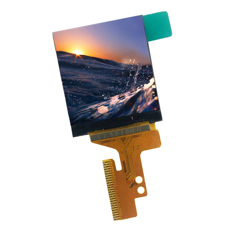
Interface, Pinout, and Backlight Driving
Lock the electrical interface before you approve any mechanical drawing. The interface type sets the pin count, the connector footprint, and the flex tail layout. Match the interface to your host board. Parallel RGB suits high refresh rates and simple timing. SPI keeps pin count low and fits small panels. MIPI DSI suits compact designs with tight routing. Confirm the pinout against your schematic line by line. A single swapped pin can destroy a customized TFT display module during first power-up. Ask your supplier for the connector part number and the mating drawing. Verify the flex tail length against the distance to your board.
Backlight driving deserves equal attention. Decide whether the driver sits on the module or on your main board. An on-module driver simplifies integration and shortens your design cycle. An external driver gives you control over dimming strategy and heat placement. Check the forward voltage and current against your supply rail. Plan the dimming method early: PWM dimming, analog dimming, or a combination. PWM dimming holds color at low levels. Analog dimming avoids audible noise from the driver. Document the connector orientation and the flex bend radius on the drawing. Add an EMC filter where the backlight cable runs near a switching supply. These details prevent a late respin.
Brightness, Viewing Angle, and Touch Integration
Set brightness from the real ambient light at the installation site, not from a datasheet maximum. A compact TFT display module for an indoor panel needs far less luminance than an outdoor unit. Higher brightness raises power draw and heat, so balance the target against your thermal path. Viewing angle follows the same logic. Wide viewing angle costs more, so specify it only where the user views the screen off-axis. Check contrast at the actual viewing angle, not only head-on.
Display and touch customization belong in one decision. Choose resistive touch for glove use and stylus input. Choose capacitive touch for multi-touch gestures and a clean front surface. Confirm the touch controller interface and its mounting points relative to the panel frame. Review the mounting hardware on the frame at the same time. Bond the touch sensor to the cover glass before final assembly. Test touch linearity at the corners, where errors concentrate. Run a noise test with the backlight on and the radio transmitting, because a switching backlight can disturb capacitive sensing.
Optical bonding affects readability. Full lamination cuts internal reflections and improves contrast under bright light. Air bonding keeps cost lower and simplifies rework. Weigh both against your depth budget and service plan.
Validate the integrated TFT display module on the bench before you commit tooling. Run a brightness sweep, check flicker at low dim levels, and confirm touch response across the full active area. Record every result against the specification sheet. This bench data becomes your acceptance criteria for production units. A disciplined electrical and optical sign-off protects the lcd display module from late changes. It also keeps the second lcd display module variant on the same electrical platform, which lowers program cost across the family.
Environmental and Regulatory Compliance
Temperature, Humidity, Shock, and Vibration
Define the operating environment before you approve a prototype. State the lowest and highest ambient temperature the product will see in service. Add the storage range, because shipping and warehouse conditions often exceed field conditions. Name the humidity level and whether condensation can form. List the shock and vibration sources: a drop onto concrete, a vehicle mount, or a pump nearby. These inputs set the test plan for your customized TFT display module.
Test to a named standard so results travel with the design. IEC 60068 covers environmental testing, including dry heat, damp heat, and vibration. Run thermal cycling across the full range and watch for condensation inside the housing. Check the display at the temperature extremes, not only at room temperature. A compact TFT display module can show slower response or reduced contrast when cold. Confirm the backlight starts reliably at the low end. Shake the unit on a vibration table and inspect the flex tail and connectors afterward.
Certifications and Compliance Planning
Map the target markets to their rules early. Safety certification under IEC 62368-1 applies to many information technology products. Ingress protection follows IEC 60529, so decide the IP rating your enclosure must meet. RoHS and REACH restrict certain substances, and your supplier should hold declarations for the panel and the adhesives. Ask for these documents during quoting, not after tooling.
Plan the compliance path alongside the mechanical design. Sealing choices affect the IP rating, and adhesive selection affects substance declarations. Build the certification samples from production tooling, because a hand-built unit may not represent the final assembly. Budget time for retesting if a change lands late. A disciplined integration of compliance checks into each design review keeps the schedule intact. The integrated TFT display module you approve should carry the same declarations as the units you ship.
Cost and Performance Trade-offs
Compare Options by Application Fit
No single option wins on every axis. Weigh each choice against technical performance, application fit, compliance, and cost together. A full-lamination cover glass improves contrast and durability, yet it adds stack height and process steps. Air bonding keeps cost and rework effort lower, and it suits products with a short service life or a generous depth budget. Rear stud mounting gives you repeatable, serviceable fastening, while adhesive bonding trims profile height at the expense of field repair. High brightness and wide viewing angle raise power draw and unit price, so reserve them for outdoor or off-axis viewing.
|
Option |
Best fit |
Trade-off |
|---|---|---|
|
Full lamination |
Bright ambient light, rugged use |
Higher cost, taller stack |
|
Air bonding |
Cost-sensitive, serviceable units |
More internal reflection |
|
Rear stud mounting |
Repeated assembly, field service |
Needs boss clearance |
|
Adhesive bonding |
Thin, low-profile designs |
Harder to rework |
|
High brightness |
Outdoor and kiosk use |
More power and heat |
A compact TFT display module for an indoor panel rarely needs the outdoor specification. Match the option to the real use case, and you avoid paying for performance the user never sees.
Tooling, Lead Time, and Volume Planning
Tooling investment, lead time, and order volume move together. Custom frames, gaskets, and cover glass need tooling, and that cost spreads across the units you build. Low volume carries a higher cost per unit. Higher volume lowers it. Tooling also adds lead time before the first production unit, so plan it against your launch date.
A semi-custom module often fits better than a full custom build. It reuses an existing panel and frame, and you add your own enclosure mounting features and mounting points. That approach shortens lead time and cuts tooling spend. Full customization pays off when volume is steady and the mechanical integration demands a unique frame. Review mounting and enclosure mounting early, because a late change restarts tooling. A customized TFT display module built on a shared platform keeps integration risk low. An integrated TFT display module with matched mounting points also simplifies assembly. Treat the lcd display module as a platform decision, and confirm the second lcd display module variant shares it before you commit.
Treat the project as a fixed sequence. Define enclosure constraints first, then customize mechanical fit, lock electrical and optical performance, validate environmental compliance, and optimize cost last. Each step feeds the next, and a customized TFT display module emerges only when every stage closes cleanly.
Your next actions are concrete. Build a requirements checklist, request mechanical drawings and samples from a partner such as Golden Vision, and validate a prototype inside the actual enclosure before mass production. Early customization of a compact TFT display module reduces total program risk, and an integrated TFT display module validated in the real housing protects your launch schedule.
FAQ
Where should you start when the enclosure already exists?
Measure the window, depth, boss positions, sealing zone, and thermal path first. Record display needs on the same sheet. Send both lists to your supplier before you compare panels. This order keeps a compact TFT display module from forcing a housing redesign later.
How do you secure a panel without stressing the glass?
Clamp the frame, never the viewing area. Integrated rear studs give repeatable mounting points that match your boss pattern. Screw plus bracket mounting suits larger panels. Adhesive bonding trims profile height for thin designs. Confirm the clamp zone on the drawing before you cut metal.
Should you choose full lamination or air bonding?
Full lamination improves contrast and durability under bright light, yet it adds stack height and process steps. Air bonding costs less and eases rework. Match the choice to your depth budget and service plan. Update the depth budget after you decide.
When is a semi-custom module the better fit?
A semi-custom module reuses an existing panel and frame, so you add your own enclosure features and mounting points. It shortens lead time and cuts tooling spend. Full customization pays off at steady volume with unique mechanical demands. Treat the lcd display module as a platform decision.
Which tests should a prototype pass before tooling?
Run thermal cycling across the stated range and check the display at both extremes. Add damp heat, then a vibration test per IEC 60068, and inspect the flex tail afterward. Confirm safety, ingress, and substance declarations early. Validate a customized TFT display module inside the real housing before release.
 Network Supported