

Choosing a tft display screen interface means balancing speed, pin count, and complexity. You weigh these three factors against your project goals. The short answer: SPI suits simple, low-speed work best. RGB or LVDS handles high-resolution video. This post compares MCU/MPU, SPI, I2C, parallel 8-bit and 16-bit, TTL/RGB, LVDS, MIPI DSI, and briefly HDMI and eDP. A tft lcd module pairs a controller with a panel, and that pairing shapes your options. Many tft displays run fine on slow serial links. Others demand video-rate bandwidth. Your tft lcd choice depends on the target. Modern tft lcd technology covers both extremes. Each tft display and lcd display variant fits different needs. Understanding lcd and tft differences helps you decide. The right interface for tft displays keeps cost and wiring manageable.
Key Takeaways
-
SPI uses only four wires and works best for low-resolution tft displays up to 480×320.
-
For high-resolution video, choose RGB, LVDS, or MIPI DSI to get enough bandwidth.
-
Match the interface to your microcontroller's pins and protocol support before picking a display.
-
I2C moves data too slowly for pixel streams. Use it for touch or configuration only.
TFT display screen interfaces overview
A tft display screen interface is the electrical link between your controller and the panel. It carries pixel data, timing signals, and control commands. The panel type matters before you pick a protocol. Each tft lcd module pairs a driver IC with a glass panel, and that pairing limits which interfaces work.
Active-matrix TFT LCD vs passive-matrix LCD
An active-matrix tft lcd gives every pixel its own transistor. That transistor holds the charge steady while the backlight shines. A passive-matrix lcd vs active-matrix tft lcd comparison shows the key gap: passive-matrix panels address rows and columns in sequence, so each pixel fades between refreshes. This difference explains why an active-matrix liquid crystal display needs faster interfaces. You must rewrite every pixel before it dims. A passive-matrix lcd vs active-matrix tft lcd choice also affects contrast and response time. An active-matrix tft lcd refreshes thousands of times per second in video mode. A tft lcd vs passive-matrix lcd decision usually favors the active type for any moving image.
Panel chemistry adds another layer. You will meet tn tft lcd, ips tft lcd, and va tft lcd variants. A tn tft lcd offers fast response at low cost. An ips tft lcd delivers wide viewing angles. A va tft lcd provides deep blacks. These tft lcd panel types share the same interface options, so protocol choice stays independent of cell chemistry.
Serial, parallel, and video interface families
Three families cover almost every tft lcd display you will wire. Serial interfaces, SPI and I2C, use few pins and low clock rates. Parallel interfaces move 8 or 16 bits per cycle through the MCU or MPU bus. Video interfaces stream continuous pixel clocks. This last group includes TTL/RGB, LVDS, MIPI DSI, HDMI, and eDP.
The family you pick shapes your whole design. A tft lcd display on SPI needs four wires. A tft lcd display on RGB needs two dozen. Video links demand a controller with a dedicated display pipeline. Serial links tolerate small MCUs. That trade-off drives every later decision in this guide.
TFT LCD interface comparison table
When you select a tft display screen, the interface type determines performance limits and wiring demands. The table below summarizes key parameters for each common interface. Use it as a quick reference before you commit to a controller and panel combination.
Data rate, pin count, and complexity
|
Interface |
Data Rate |
Pin Count |
Typical Applications |
Complexity |
|---|---|---|---|---|
|
SPI |
≤50 Mbps |
3–4 |
Low-resolution tft lcd up to 800×480 |
Low |
|
I²C |
≤3 Mbps |
2 |
Configuration only, not for image data |
Very low |
|
RGB / TTL |
≤100 Mbps |
16–24 |
Small to medium lcd display up to 1024×768 |
Medium |
|
8-bit parallel |
~30–50 Mbps |
10–12 |
Low-res tft lcd module with built-in frame buffer |
Low–Medium |
|
16-bit parallel |
~60–100 Mbps |
16–18 |
Medium-res tft display with frame buffer |
Medium |
|
LVDS |
≥1 Gbps |
4–8 pairs + clock |
High-resolution tft lcd up to 1920×1080 |
Medium–High |
|
MIPI DSI |
1–6 Gbps |
1–8 lanes + clock |
Smartphone and tablet display up to 4K |
High |
|
eDP |
2–8 Gbps |
2–4 pairs + AUX |
Laptop and large format tft lcd panels |
High |
|
HDMI |
≥18 Gbps |
19+ pins |
Consumer monitors and TV liquid crystal display |
High |
The data rates listed represent practical maximums you can expect with proper PCB layout. Pin count includes required signals only. Power and ground connections increase total wiring. Complexity covers both hardware design effort and software initialization depth.
SPI offers the simplest hookup but limits resolution to 800×480. You cannot push high-definition video through a four-wire serial link. I²C moves even less data and serves best for touch controllers or temperature sensors inside the module. For any moving image, avoid I²C as the primary pixel bus.
RGB/TTL and parallel interfaces provide a middle ground. You get moderate resolution support with manageable wiring. The 8-bit and 16-bit parallel options work well with MCUs that have built-in parallel memory controllers. These interfaces require a frame buffer inside the display itself, which adds cost for larger resolutions.
LVDS and MIPI DSI represent the video-rate family. LVDS uses differential pairs to push data at gigabit speeds with low electromagnetic interference. You see it in automotive tft lcd panel types and industrial displays. MIPI DSI achieves higher throughput with fewer wires. Most modern application processors integrate MIPI DSI controllers directly.
eDP and HDMI target consumer-grade applications. eDP reduces pin count compared to LVDS for resolutions above 1600×900. HDMI dominates in monitors and television sets. These interfaces require dedicated transmitters and careful impedance matching.
Typical applications per interface
SPI fits low-resolution tft lcd technology like the common ILI9341 or ST7789 drivers. These controllers include internal frame buffer memory, so the host MCU only sends updates when the screen content changes. This approach works for menu displays, instrument clusters, and simple animations. Resolution peaks at 800×480 regardless of physical panel size.
I²C rarely drives a tft display directly. Use it for configuration of an lcd and tft driver chip or for reading touch coordinates. The bus speed caps at 3 Mbps, far too slow for pixel data.
RGB/TTL and parallel interfaces suit 3.5-to-7-inch tft lcd displays in handheld instruments and embedded panels. The 16-bit parallel variant delivers smooth video playback at VGA resolution. You need a processor with enough GPIO pins or a dedicated parallel LCD controller.
LVDS dominates the 7-to-15-inch tft lcd market. Single-channel LVDS handles 1280×800 at 60 Hz. Dual-channel LVDS pushes 1920×1080. Automotive grade panels tolerate cable runs up to two meters. This interface also resists noise better than single-ended parallel links.
MIPI DSI appears in smartphones, tablets, and embedded tft lcd modules. This interface supports flexible lane count. Four lanes at 1 Gbps each deliver smooth 1080p video. Power consumption stays lower than parallel alternatives, a critical advantage in battery-powered products.
eDP replaces LVDS in modern laptop tft lcd panels and high-end embedded lcd display systems. The auxiliary channel carries configuration commands and supports features like Panel Self Refresh for power savings. You get 4K resolution with only two differential pairs, supporting a wide range of tft displays.
HDMI connects tft displays to consumer video sources. For embedded projects, you typically add an HDMI transmitter chip, which increases component count and board space. Use it only when you require direct compatibility with standard video outputs.
Pros and cons of serial interfaces
SPI strengths and limits
SPI cuts pin count. You connect a tft lcd with only four wires. This makes the interface practical for low-cost microcontrollers. A parallel tft lcd display needs many ports. SPI frees those pins for other tasks. Many tft lcd modules include a frame buffer. The host sends updates only when content changes. A simple tft lcd design benefits from this low-pin approach. Developers choose SPI for many tft lcd projects because it simplifies wiring. A typical tft display on SPI runs at moderate speeds. This tft lcd interface suits many embedded projects. The tft lcd controller handles most timing internally.
SPI is slower than parallel alternatives. Repetitive color fills expose this weakness. Each pixel needs full color transmission. The protocol wastes bandwidth on consecutive same-color pixels. Some tft displays accept higher bit rates in parallel mode. An external shift register accelerates uniform fills. You load the color once. You toggle the write strobe rapidly. This adds cost and complexity though. Speed gains depend on content. Uniform fills benefit most. Complex images see little improvement. Despite these limits, SPI suits cost-constrained designs well. A low-resolution tft lcd on SPI works fine for menu displays. Each tft lcd you wire this way keeps complexity low. An SPI-based tft lcd keeps your bill of materials low.
I2C strengths and limits
I2C uses only two wires. This lcd display interface offers the simplest hookup. You set driver registers over this bus. This interface lets you control the display with two wires. The I2C interface also supports multiple devices on one bus. The bus also runs on shared wiring with sensors. I2C cannot drive a tft lcd directly though. The speed caps at 3 Mbps.
That rate falls far below what any display needs for pixel data. Use I2C for auxiliary functions only. The comparison of lcd and tft options makes this clear. Modern tft lcd technology relies on faster pixel links. I2C remains a support bus. Pair it with SPI for image data on a tft lcd. Avoid I2C for any moving image content.
Pros and cons of parallel and video interfaces
MCU/MPU 8-bit and 16-bit parallel
An 8-bit or 16-bit parallel tft lcd moves data over multiple wires at once. You gain speed over SPI. A 16-bit parallel tft lcd reaches roughly 60–100 Mbps. That rate supports medium-resolution video on a tft display. The host writes directly to the panel bus. You need a controller with enough GPIO pins. A 16-bit link consumes 16–18 signal lines. That pin count strains small MCUs.
The parallel tft lcd module often includes a frame buffer. The buffer stores one full image. Your MCU updates only changed regions. This design keeps the tft lcd interface manageable. Wiring grows complex as resolution rises. Signal degradation limits cable runs. You cannot place the panel far from the board. A parallel tft lcd suits handheld instruments and embedded panels. It does not scale to high-definition video.
TTL/RGB, LVDS, and MIPI DSI trade-offs
These three video interfaces target different priorities. TTL/RGB sends parallel R, G, B and sync lines. It suits QVGA to WVGA resolutions. The design stays simple and works with many MCUs. Pin count runs 16–24 lines. Power consumption stays higher than serial alternatives. TTL/RGB cannot handle long cables or high refresh rates.
LVDS and MIPI DSI both use differential signaling. LVDS reaches up to 3.125 Gbps per lane. It handles 1920×1080 at 60 Hz with a typical 4-lane setup. Cable runs reach up to 10 meters. Noise immunity is excellent. Industrial monitors, medical devices, and automotive clusters rely on LVDS. The tft lcd technology behind these panels tolerates harsh electrical environments. Drawbacks include higher power than MIPI and bulkier connectors.
MIPI DSI pushes up to 4 Gbps per lane. It uses 1 clock lane plus 1–4 data lanes. Pin count drops to 8–12 for a 24-bit RGB equivalent. PCB complexity stays low. Power consumption is the lowest of the three. Smartphones, tablets, and wearables depend on this interface. Cable length caps at 1 meter. Noise immunity is moderate. You need specialized hardware and driver support. For compact tft displays, MIPI DSI wins. For rugged, long-distance tft lcd display systems, LVDS remains the safer choice.
Choosing the right TFT LCD display interface
You now know how each interface behaves. The final step maps your project needs to one choice. Start with your controller, then check resolution and refresh rate. Budget and wiring follow from those two answers.
Match the interface to your MCU or processor
Your processor decides more than any other factor. Check the datasheet first. Confirm the chip supports the protocol natively. A small MCU with four free pins cannot drive a 24-bit RGB bus. It can drive a tft lcd over SPI with four wires: MOSI, MISO, SCLK, and CS. That same chip runs I²C on two wires for touch control.
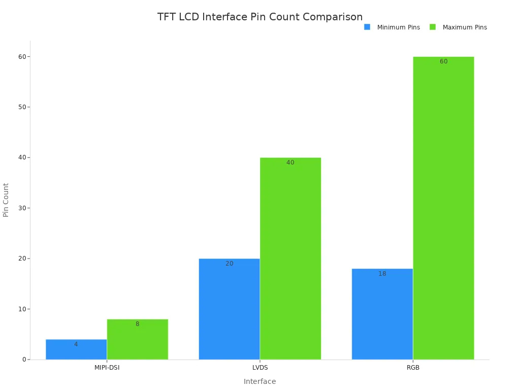
Pin count drives cost and board space. SPI needs 4 pins. I²C needs 2. An 8-bit parallel tft lcd needs 11 or more. RGB demands 18 to 60 pins. MIPI DSI and LVDS use 4 to 8 lanes plus clocks. Fewer pins mean a smaller FPC and less EMI risk. More pins mean faster refresh and lower latency.
Watch the voltage gap too. A 1.8 V processor and a 3.3 V tft lcd module need level shifters. That extra part adds cost and board area. Verify panel availability as well. Some tft lcd models ship in only one interface type. Mechanical limits matter here. A wide FPC may not fit your enclosure. EMI-heavy settings often favor LVDS over MIPI. This tft lcd module selection logic keeps your design realistic.
Match the interface to resolution and refresh rate
Bandwidth sets the ceiling. Use this relation: bandwidth in bits per second equals width times height times refresh rate times color depth times an overhead factor of roughly 1.2 to 1.5. A 1024×600 tft lcd at 60 Hz with 24-bit color needs far more throughput than a 320×240 panel.
The evidence table shows the practical ranges. SPI handles up to 800×480. Parallel MCU links reach 800×480. RGB/TTL covers 480×272 to 1280×800. LVDS spans 800×480 to 1920×1080. MIPI DSI reaches 4K. HDMI also reaches 4K.
Pick SPI for simple, low-speed designs. Pick RGB or LVDS for high-resolution video.
That rule of thumb holds across most projects. A menu screen on a tft display needs no video link. A moving map or camera feed does. The tft lcd technology inside your panel sets the pixel clock limit. The liquid crystal display cannot refresh faster than its driver allows. Match the interface type to that limit, not above it.
Budget closes the loop. Serial links cut wiring and connector cost. Video links raise both. A tft lcd display with a built-in frame buffer lowers host load. A bare panel shifts that work to your processor. Weigh speed against pins, wiring, and cost. Then choose the tft lcd that fits. The right tft lcd display keeps your lcd and tft trade-offs balanced. Two tft displays may share a panel but differ in interface. Two tft lcd modules may share a size but differ in speed. Your tft lcd choice should follow the data, not the trend.
SPI stays simplest for low-speed projects. A tft lcd on SPI uses four wires. For video, pick RGB, LVDS, or MIPI DSI. Your tft lcd display choice must balance speed, pin count, and cost. Each tft lcd interface suits a different tier. The lcd and tft market spans these options. Your lcd display choice starts from processor capabilities. Most tft displays work best when you match protocol to controller. A tft lcd module with wrong link creates bottleneck. Know your tft lcd requirements. Select the tft lcd that fits your hardware. A tft lcd chosen this way avoids over-engineering. The right tft lcd keeps your project efficient. Start from your MCU and target resolution. Do not default to the fastest tft lcd. These tft displays benefit from careful tft lcd interface selection.
FAQ
Can SPI drive a high-resolution tft lcd?
No. SPI supports up to 800×480 resolution only. A tft lcd with higher pixel counts requires parallel or video interfaces. Check your target resolution against SPI bandwidth before choosing this link.
Does I2C work as a primary pixel bus?
No. I2C caps at 3 Mbps. A tft lcd cannot receive pixel data through this slow bus. Use I2C for configuration or touch input only. This interface serves auxiliary roles, not image transport.
Which interface suits battery-powered tft lcd designs?
MIPI DSI. It uses fewer lanes and lower power than parallel alternatives. A portable tft lcd benefits from differential signaling. You get high throughput without draining your battery quickly.
What separates RGB from LVDS?
RGB sends single-ended signals on many wires. LVDS uses differential pairs. A tft lcd with long cable runs needs LVDS for noise immunity. Choose RGB for short connections and lower complexity.
Does processor choice matter more than resolution?
Yes. Your MCU determines available pins and protocol support. Match every tft lcd interface to your controller first. Resolution comes second. A mismatched link creates a bottleneck your processor cannot fix.
 Network Supported